Search This Blog

Saturday 30 December 2017

Sketchup + FormIt = Revit?

Many of my students have incredible Sketchup skills, mostly due to the fact that they were taught Computer Aided Design through Sketchup from their varsity days. I am sure that many of the Revit Recess readers themselves have completed an amazing design or two. For those with no Sketchup experience, do a quick internet search for something along the lines of "Amazing Sketchup Designs" to see for yourself.

However, if you want to, need to, or are "forced" to be at the forefront of technology (Let's be brutally honest, working in and through cloud is the future whether we like it or not) the likelihood of being exposed to the market leaders in design software in the workspace is inevitable. Now, before this post turns into a "Revit is best", "Microstation is better", or "Nothing beats paper impregnated with Potassium Ferricyanide", it is not the aim of this entry.

The aim is to discover how we can use Sketchup in conjunction with other software, such as Autodesk FormIt and Autodesk Revit.

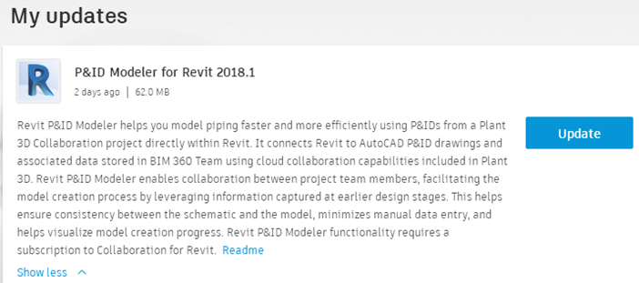
Quite a while ago, Autodesk introduced FormIt as, in my opinion, a competitor to Sketchup. A number of advancements were made to the software since its release under the Autodesk brand, one of which is an add-in for Revit called FormIt Converter. Is it perfect? No. Is it getting close to perfect? Maybe. Is it usable? Definitely!

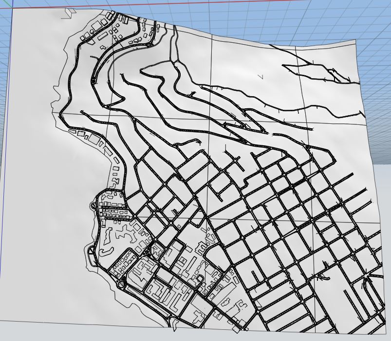
A quick search on Sketchup's 3D Warehouse site got me a simple-ish model of a Velociraptor skeleton.

This Sketchup Skeleton will go through 3 steps in order for it to be useable in Revit. First of all, the FormIt Converter add-in can be found in the Add-Ins tab, FormIt Converter panel. When selecting the Convert RFA to FormIt icon, you will find four options: Convert RFA to FormIt, Convert SKP to FormIt, Import FormIt to RVT and Reload Families.

In order to use a Sketchup object in Revit, we need to Convert it to a Formit file first (.AXM file format)

You will be prompted to specify a path to the Sketchup file, as well as a folder path to where the FormIt file will be saved.

Depending on the complexity of the Sketchup object, the converter will provide either a Succeeded or Failed result. More about the failures will be discussed at the end of this post.

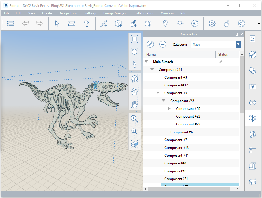
There are a few similarities between Sketchup and FormIt, one of those being that one works in layers. All of the Skecthup layers will be brought into FormIt.

Once the above process has run its course, it is time to Import the Formit family into Revit. This is where a negative comes into play. When downloading Sketchup objects, rather stick to a Sketchup 2016 format. I have only experienced conversion failures with Skecthup 2017 and 2018 objects. The second negative is that, due to a Sketchup 2016 file being used, all of those individual layers will be seen as nested families. In other words, go and make yourselves a couple of coffees while the upgrade process for each layer takes place.

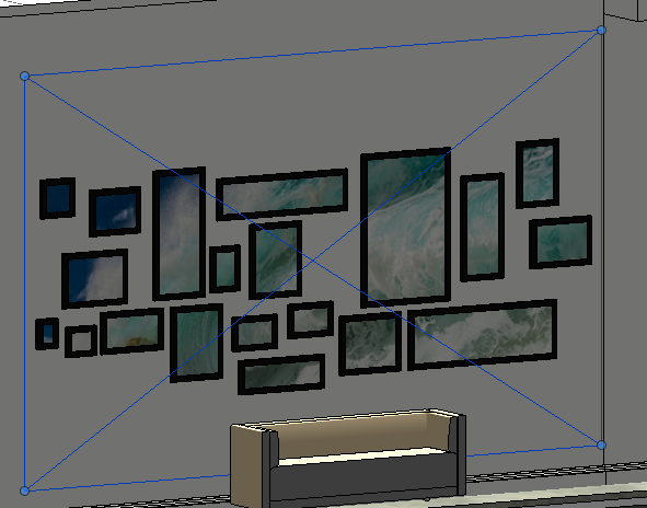
The end result could look similar to the image below.
 "Depending on the complexity of the Sketchup object" has been raised earlier. The more complex the object is, the more triangulations and quads existing in the geometry, the more likely it is that the conversion will fail. Another consideration is the overall file size: 2MB Sketchup file converted to a 4.4MB Formit file, which blows up to a 29.4MB Revit project file size (Fully purged)  

I guess that the message I want to convey is that one can use Sketchup objects in Revit, but it should be used very sparingly. Even better, rather design those Sketchup objects in FormIt from the start. Not only will you feel familiar with FormIt's user interface, commands and geometry manipulation, but you will also drastically decrease your overall project file size.

Have a great new year folks!

Friday 15 December 2017

Split Canvas Prints in Revit

Splitting one print across multiple canvasses in Revit is easier than you think.

This Revit Recess entry will explain the steps:

First of all, one will need to create canvas frames. This can easily be done by creating a simple extrusion with a height above finished floor level, frame height, frame width, and frame depth parameter; all instance based.

The next step would be to create a random pattern of these frames on a wall. Due to the dimensions of the frames being instance parameters, we can easily push and pull the frame sizes and heights to what we would like.

You might have noticed that no backing was created for the frames. This is where the "trick" comes into play. The backing can be created as a fully transparent wall, 5mm in thickness. This will be our canvas.

By changing the workplane of your view to the front face of the wall added in the previous step, you can place and resize a decal image of your canvas image to suit your needs.

The end result?

Monday 23 October 2017

Recreating History: Pretoria 1947

"Photogrammetry is the science of making measurements from photographs, especially for recovering the exact positions of surface points. Photogrammetry is as old as modern photography, dating to the mid-19th century and in the simplest example, the distance between two points that lie on a plane parallel to the photographic image plane, can be determined by measuring their distance on the image, if the scale (s) of the image is known." - Wikipedia

Have you ever wondered how your hometown looked 50+ years ago? Well, if you have access to Recap Photo and some old aerial photos you will very likely be able to recreate your own piece of history. I sourced some old aerial photos of Pretoria, South Africa from the Institutional Repository of the University of Pretoria and by using Recap Photo, achieved some amazing results!

The images below are of individual aerial photos taken in 1947. I was amazed by how rural some areas were - Areas where today there are major residential, commercial and industrial sites.  

Within Recap Photo, one can create a new 3D project using either the Aerial or Object functionality. Aerial is used for UAV and drone photos (Where one could have GPS data assigned to the photos) and Object is used for applications other than drones or UAV's.

The process of photo to mesh conversion takes place in 3 stages: Uploading the photos, registering the photos for mesh creation and lastly downloading the 3d model as a .rcm file.  

The end result? If there is enough overlap between the aerial photos you will be able to generate a 3D model with minimal user input. Are you excited? I definitely am!

Tuesday 3 October 2017

Toposurface From Infraworks Model - Success!

In the beginning of 2015, I created a post where Infraworks' Model Builder capability was outlined. Since then, we have done numerous tests to see how far the software will get us - 2 Years later, I posted that in Revit 2018 one can link a Coordination Model (Navisworks file) which may be used for site planning. At that time, I could however not find a way of generating a toposurface from the Coordination model.

Enter my colleague Mitchell Parsonage, who managed to create a workflow with three easy steps :

1. Define your site extent in Infraworks and export to an OBJ format


2. Import the OBJ into Autodesk Formit, and Export to DXF

3. Link the DXF into Revit and generate a Toposurface from the Import


4. The end result? Nicely done Mitch!

Friday 15 September 2017

Revit Detail Item Source Files

Based upon the success of the post: Revit Planting RPC Source Files, I thought it would be a good idea to create a Detail Item Source File which Revit Recess readers can download. So I started working on a source project, laying out the different detail item family divisions, intending to group and sort each detail item family accordingly.

I soon realized that doing something like this in my off-time would take quite some time. I have however found a Eureka moment while rummaging through the default content library.

If you have installed the UK content, have a look at the Detail Items folder. You will notice a DWF file called "DetailComponents-Browsable-PlotableSheets" in which all of my planned work was already done.

This DWF will contain previews of all the UK content Detail Item families, already grouped and sorted into their different Divisions.

By the way, did you know that there is an updated Autodesk Design Review you can download for free? No more working in Design Review 2013.

Have a great weekend, folks!

Thursday 14 September 2017

3 Categories for one element?

I recently experienced some very strange behavior on a client model. Three "categories" for one element. You might be thinking: Impossible!

One does however stumble across some strange things in Revit, with some of my favorites highlighted in Luke Johnson's blog: What Revit Wants

Getting back to the "three category element" though - While doing a bit of family maintenance on a project, I came across these diagonal lines: Looks like Reference Planes, right?

Not really.... Revit sees it as Linear Dimensions....

When navigating to a referring view, however, they are seen as camera views... Has any reader experienced this yet, and even better: Found the reason?

Tuesday 5 September 2017

AU South Africa - The Countdown Begins!

As a lot of Revit Recess's South African readers will already know, Autodesk University South Africa takes place on 8 September 2017 at the Century City Conference Centre, Cape Town. Only 3 days to go, everyone!

This year's event is sure to be bigger and better than last year (Which already exceeded our expectations).

Should you require more information on the event, feel free to follow the links below:
* Pricing
* Agenda & Track Descriptions
* Speakers
* CPD Points
* Design Competition
* Venue & Accommodation
* Sponsors
* Gallery

As mentioned in previous posts, we have a lot of exciting things in store for all attendees, making this event well worth your valuable time. An example of one of these is the Modena selfie frame. Feel free to take some photos and have Autodesk University South Africa trending on your social media platforms: #ModenaInAction #AUSouthAfrica


Tuesday 29 August 2017

Revit 2018.1 - P&ID Modeler Explained

"P&ID Modeler streamlines the process for modeling in Revit based on P&IDs and ensures consistency between the P&ID drawing and the Revit model.
Use P&ID Modeler to:
  • Enable collaboration between project team members, including re-use of data captured at earlier stages.
  • Simplify the creation of the model from early stage schematic deliverables, by minimizing manual entry.
  • Validate consistency between the 2D schematic and the 3D model.
P&ID Modeler is intended to replace the manual workflow of creating a 3D model with the guidance of a printed P&ID drawing. Use it to create a 3D piping model directly from a 2D P&ID. Status indicators make it easy to track what has been modeled and what remains to be modeled."
          - Autodesk

This is a step in the right direction. Autodesk has recently released an update for Revit called P&ID Modeler for Revit 2018.1. As highlighted in bold above, this update will not be a one-click-wonder to automatically convert a P&ID drawing to intelligent geometry.

So, how does this update work? This Revit Recess entry will take you through the steps.

1. The P&ID Modeller is only applicable for Revit 2018.1, and can only be downloaded through the Autodesk Desktop App.

One needs to either have received a link to collaborate with a P&ID drawing, or have access to Plant 3D to properly use this workflow. Through Plant3D, we can share the entire P&ID model to the cloud. Collaboration > Project > Share Project.

The sharing of the P&ID drawing takes place over BIM360 Team.

We need to choose a Hub and Project folder to which the P&ID drawing must be uploaded. Obviously the project folder needs to be set up over BIM360 Team’s website first.

Depending on the file sizes and your internet connection, it might take some time to upload these files.


As this is a BIM360 Team model now, the usual BIM 360 Team functionality is accessible, such as inviting team members, changing permission settings, viewing who has uploaded files, made changes, etc.


In Revit 2018.1 (Provided the add-in is installed), you will see the P&ID Modeller icon (Systems > P&ID Collaboration > P&ID Modeler). You will also see another panel window specific to the add-in. If you cant see the panel window, enable it by going to View > Windows > User Interface > P&ID Modeler.
Please note that to use the add-in, you need to have an active C4R (Collaboration for Revit) license. Another note: I have found that trying to sign into your Autodesk Account through Revit does not work - Signing into your Autodesk Desktop App automatically signs you into Revit, which allows you to start the collaboration process. All that needs to be done now, is to select the P&ID project you would like to use in Revit.

We need to select a Plant 3D paper space layout which we would like to use in Revit. Note that you will struggle to access the drawing with a bad internet connection. 

The Plant 3D model will now contain all pipe segments complete with all their respective fittings, valves, accessories, tags, etc. 

When selecting a fitting in a pipe segment, we will get a warning that Revit cannot map or match the P&ID part to a Revit family. Similar to Fabrication Parts, we have to tell Revit which family needs to be mapped to which P&ID part

This can be defined through the P&ID Modeler settings. The Revit families loaded into your project will determine how the add-in automatically maps Plant to Revit. It seems like the families which are highlighted in green has common words in the family and type name, but the entire name does not match (Although I have not yet confirmed this).

When selecting a pipe segment from the palette window, Revit will identify and highlight the P&ID segment in dark blue – As the P&ID drawing also contained blue lines, it became a bit difficult to see where in the drawing I was. I searched for a way to change these colours, but could not find it yet. Revit’s Pre-selection, Selection and Error colours did not make a difference.

In a nutshell, you can either pick an existing Revit pipe and through the palette window, right click on a pipe segment and choose map existing. This will create a monitoring relationship between the Revit pipe segment and the P&ID pipe segment. Alternatively, you can sketch Revit pipe segments by just clicking on the P&ID pipe segment and drawing your pipe in the Revit view. 

As stated in the introduction to this post, the idea behind the P&ID functionality is that the operator can visually see if he/she has modeled everything within the P&ID file by simply looking at the palette window. 

Note: An unmapped segment/fitting/accessory will show with a black line to the left side on the window panel, a mapped and unconnected piece in yellow with green hatching, and a mapped and connected piece in solid green


This new update has certainly interested me, especially if we look at what other functionality can be created. Just imagine having the ability to convert an entire P&ID model complete with the correct equipment, fittings, valves and accessories with only a few clicks? 

Have a good day folks!

Monday 21 August 2017

Alternative Visualization Methods - Part 3

It has been a while since my last blog entry, but works happens, hey?

Creating interesting visualizations in Revit is a hobby of mine and this blog entry will form part of the Alternative Visualization Part 1 and Alternative Visualization Part 2 series. All of these posts focus on what Revit can natively do - Without using any other program, even Dynamo.


"There are no extra pieces in the universe. Everyone is here because he or she has a place to fill, and every piece must fit itself into the big jigsaw puzzle" - Deepak Chopra
The first example evolved from seeing how one can create a puzzle effect visualization to investigating what effects multiple callouts by sketch would have on project file performance. However, lets see how it was created first, before looking at the negatives, shall we?

A puzzle grid was created and callouts by sketch were added using the individual puzzle piece lines as placeholders for the callout boundaries.

Making use of wide detail lines added a bit more depth perception when all pieces were placed on a sheet. The completed image provides quite an interesting result.

The negatives to this method? First of all, it takes a loooong time to set this up. A callout by sketch does not have the functionality to create circles or arcs - Thus a rounding needs to be created by sketching many small straight line segments. Having many of these callouts by sketch drastically affects the projects performance as well.

"The sky takes on shades of orange during sunrise and sunset, the colour that gives you hope that the sun will set only to rise again" - Ram Charan

Can you create a visualization where only a specific area show in hidden lines, and everything else in colour? The short answer is yes.

We will yet again make use of a callout by sketch, but this time a masking region will come into play as well. With a few visibility edits, the border/boundary lines of the callout and masking region was hidden.

The callout view itself was changed to a hidden lines representation, and its boundary hidden as well.

And the end result?

"I love everything that's old - old friends, old times, old manners, old books, old wine" - Oliver Goldsmith
Paging through a friend's printed visualization portfolio I wanted to do the same in Revit. Partly due to the challenge and partly because we need to save some trees.

For this challenge all that was needed was a book family, and some decal images.

Selected 3d views were rendered and saved as image files, and cropped to simulate the image being printed over two pages. Aligning them together was less of a hassle than I initially thought.

However, a strange thing happened when I tried to RayTrace the view - It looked like Revit was cutting through my book.... It could be due to the curvature of the pages or it might be due to something obscure.

None the less, I created a test render of the same view with the latest Enscape version and I was more than just satisfied with the result!

Have a great week, folks!