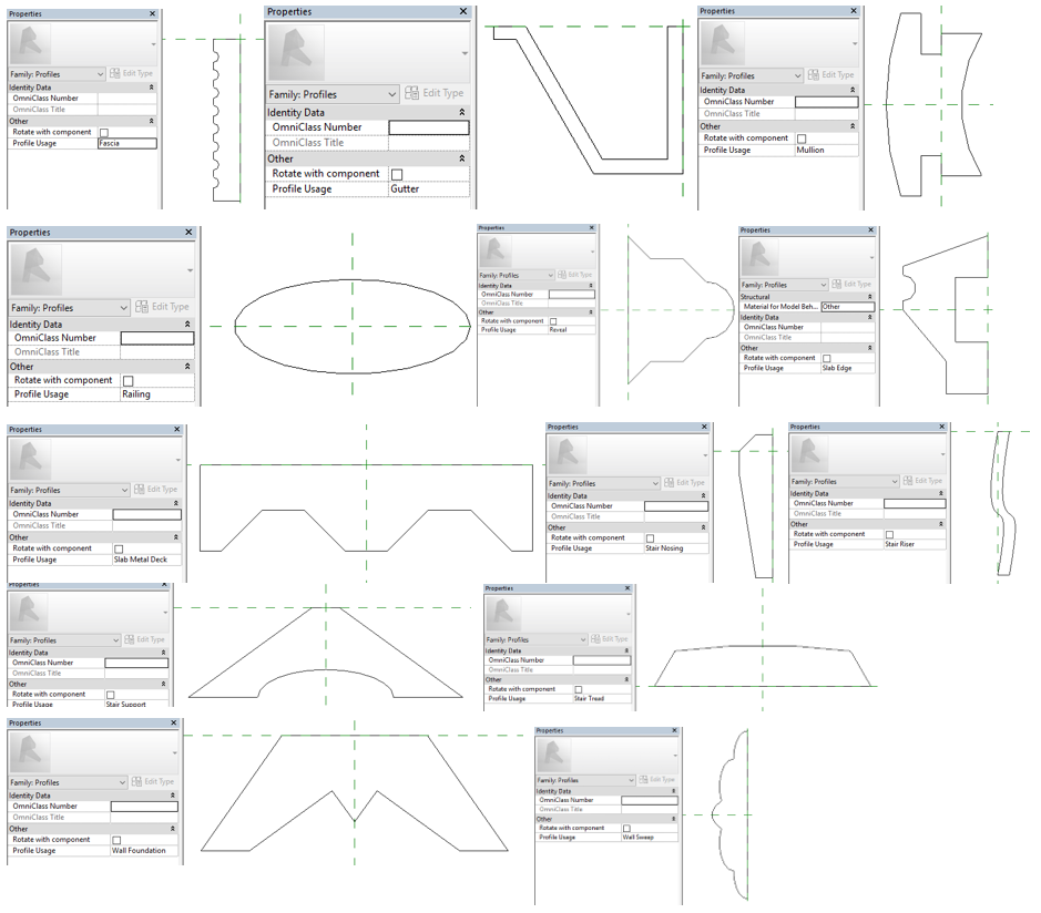
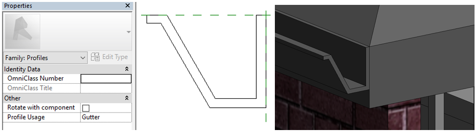
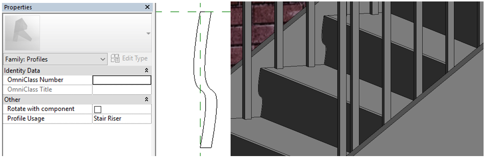
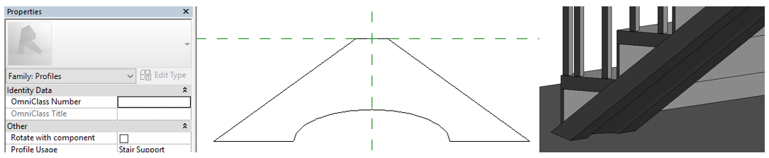
How many times have you created profiles from the default template and found that it shows up everywhere? Gutters for wall sweeps and reveals? Fascias for stair treads? This Revit Recess entry will explain the different Profile Usages one has access to.
The below image contains all of the different profile usage options available to us. Every one will be shown separately.
As the year comes to a close, it's always good to reflect back on what you have managed to achieve during the year.
I often refer to Bryan Dyson's (Former CEO of Coca Cola) speech when trying to balance my work and personal life:
“Imagine life as a game in which you are juggling some five balls in the air. You name them – Work, Family, Health, Friends and Spirit and you’re keeping all of these in the air.
You will soon understand that work is a rubber ball. If you drop it, it will bounce back. But the other four balls – Family, Health, Friends and Spirit – are made of glass. If you drop one of these; they will be irrevocably scuffed, marked, nicked, damaged or even shattered. They will never be the same. You must understand that and strive for it.
Work efficiently during office hours and leave on time. Give the required time to your family, friends and have proper rest. Value has a value only if its value is valued.”
Enjoy the festive season, enjoy the break and most of all: Rest - There is nothing wrong with being a couch potato for a few days. Recharge those batteries! Otherwise...
Paulo Coelho once said: "How much I missed, simply because I was afraid of missing it."
If you have missed Autodesk University this year, start making preparations now for 2017. There might be time constraints, you might not have the finances, you might have a big project coming up, you might, you might, you might...
That "might" sounds like an opportunity you are already missing. Trust me, AU is absolutely worth every Rand, Penny, Dinar and Dollar! Make some time now, start saving now, start planning now.
I would like to highlight two classes which literally blew me away, and I insist that you download their class materials when it becomes available on the Autodesk University website:
* Habits of Highly Effective BIM Managers: James Vandezande - Director of Design Technology at HOK * Design Strategies with FormIt 360: Jarod Schultz - Design Technology Director at initial.aec
I have to admit, I also missed a few opportunities at AU this year. I missed the opportunity of cloning myself to attend all the classes I wanted to. Next year AU, next year... All that is left to do is to get over this jetlag
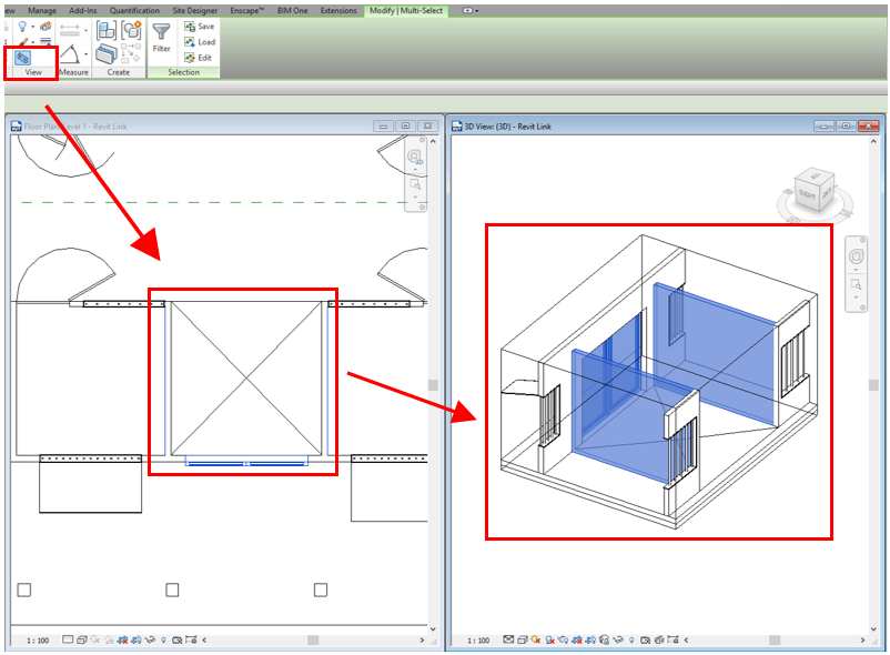
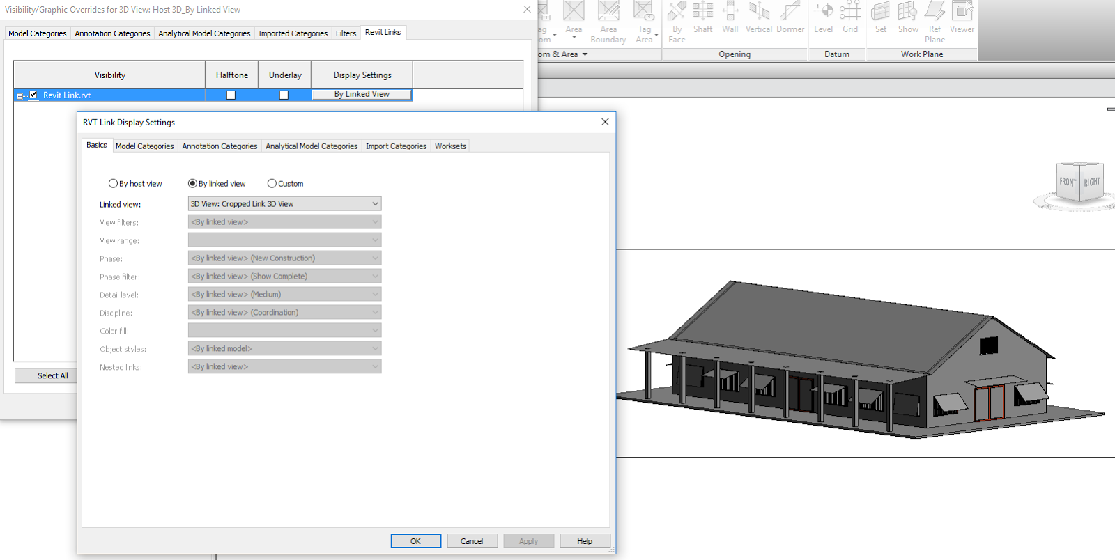
The Selection Box function in Revit is one of the most useful tools we have to quickly create a 3D view of selected elements. However, there is a wish I would love to be addressed in the Update Release or new version
I have linked a project which contains many 3D views where the crop boundaries have already been adjusted to isolate a specific area. I would like to create my own 3D view, edit the link's Visibility Graphics and set the Display Settings to the corresponding linked view - In theory that should also adjust my view's cropped region, right? Unfortunately, no luck here. Would be a nice to have though...
Even though this prestigious event happens in less than 8 days from now, if you have not had the time or finances to attend it, keep an eye on au.autodesk.com. All class modules and handouts will be uploaded in due time. Autodesk has some major developments in store for us! Sooooo.... What can you expect to experience?
If you are indeed attending the event, feel free to connect with me on the Autodesk University App - I would love to meet you all. See you in Vegas!
Having demonstrated decades of unwavering commitment to our clients with unparalleled levels of support at all levels, Modena Design Centres is proud to announce that it has been awarded the prestigious PLATINUM Partner status by Autodesk and is now the only Autodesk partner in Africa to hold this status!
Thank you to all our clients for giving us the opportunity to realise this milestone. We look forward to heading into ...the Future of Making Things with all of you, better, faster and stronger than ever before!
There is has never been a better time to contact Modena to discuss how we can help you give your company the competitive edge it deserves.
Official description for this status by Autodesk:
The Autodesk Platinum Partner designation indicates a significant investment in consulting and development services. These Partners have also demonstrated an ability to deliver the highest level of solution expertise, service, support, and customer satisfaction.
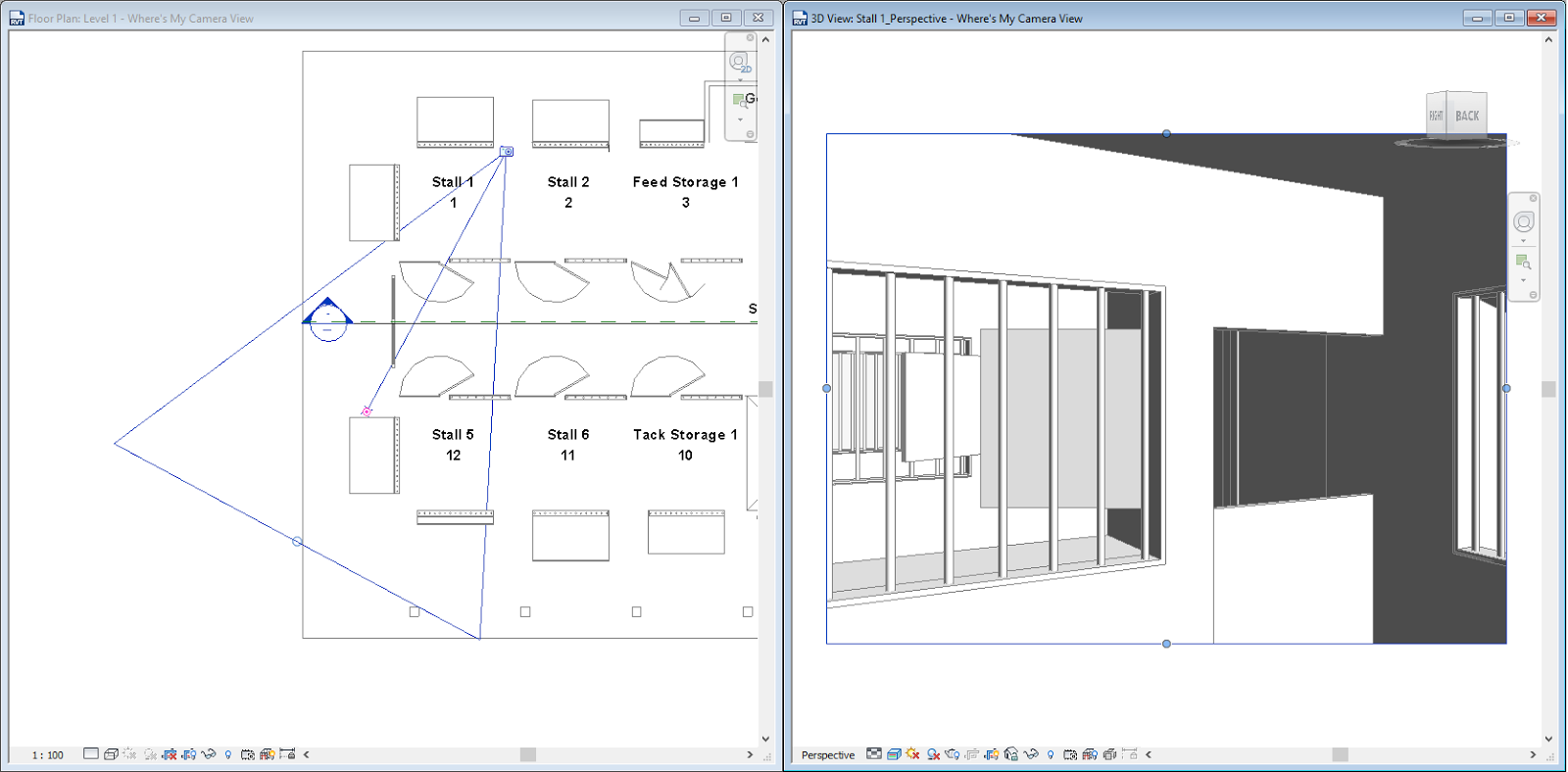
Many Reviteers still use the old method of locating their perspective camera views on their floor or ceiling plans: Tiling the windows and selecting the perspective view's crop boundary to make it visible on the plan view.
A quick and easy way of finding those pesky camera views, is to simply right-click on the View in your Project Browser, and select Show Camera. The camera position will be shown in any view: 3D, floor-, ceiling-, structural plan, even sections and elevations. There is always a workaround. we just have to find it.
Virtual Reality (VR) is the current buzz word in the built environment, and rightly so: Nothing blows a clients' mind more than walking through their own building before the groundworks have even started.
There are many benefits to experiencing a Revit model through Virtual Reality:
* Simulation: A model can be simulated in Virtual Reality to minimise potential changes that are normally made throughout the construction timeline, as well as to fine tune the construction processes. * Immersive design exploration: All project stakeholders, from the client to consultants to construction team can walk through the design, and see/scrutinise/approve every single detail of the model * Viability: Will the design be constructible? Will the client now fully understand the initial design?
Only these 3 advantages listed above already has most professionals at the end of their seats - Think about how much costs and time I can save! Think about how more productive my team can be! I am at the forefront of technology! Now don't get me wrong: I am in full agreement with these advantages and statements. However...
For a design, irrespective of whether its an architectural design or building services design to be fully immersive, accurate to a needle point and real as can be, one will need a Revit (Or any other software program) model that has been modelled to the nth degree (And accurately at that!).
This is the stage where the golden egg turns rotten for me. We have finally arrived at a stage where AEC professionals have realized that it is not necessary to model everything in 3D - The most important part of the BIM process is the Information we add to those families / blocks / objects. If you don't need to render an object or area, if you don't need to run a clash detection for an object or area, if you don't need to schedule an object or area: You do not need to model it. I know that most BIM Specialists will lynch me for this statement, but people: Let's acknowledge how the real world works. We have insane deadlines. We need to cut operating and budgetary costs at every angle possible. We have to design and manage 10 other projects at the same time. I recently saw the bad side of a Virtual Reality Revit model: Every single component was modelled in 3D. This specific project for a two storey luxury residential house. An absolutely stunning design, beautiful families, amazing renders, animations and VR capabilities. However.... This two storeyresidential house's architectural model size was 950 MB in file size! My poor client has quadrupled his coffee intake to simply investigate the architect's design to formulate his design, and it was not due to stress: One word: Lagging - Hint: That blue circle in the center of your screen spinning around, and around, and around... The biggest concern I have today, is how can you justify the waiting time as billable time? How can the architect justify the time spent to "dumb-down" the model for project stakeholders as billable time? In my opinion, we either need to get some VR protocols for model development in place ASAP, or somehow, the coding of all BIM software should change to accommodate an immense amount of detail which will ensure a smaller file size and have a smaller impact on a computer's processing power. Your thoughts?
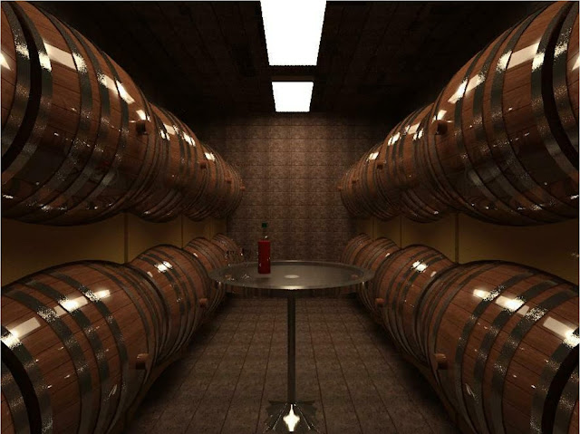
Materials assets in Revit have their own unique properties and characteristics; with Wood, as an example, having dedicated Finish properties.
This Revit Recess entry will show how each one of these wood finishes will look like in a render.
1. Finish: Unfinished
2. Finish: Satin Varnish
3. Finish: Semi-Gloss Varnish
4. Finish: Glossy Varnish
I still find the coding behind software programs like these absolutely fascinating, and at the same time way over my current capabilities (And I am absolutely OK with that)
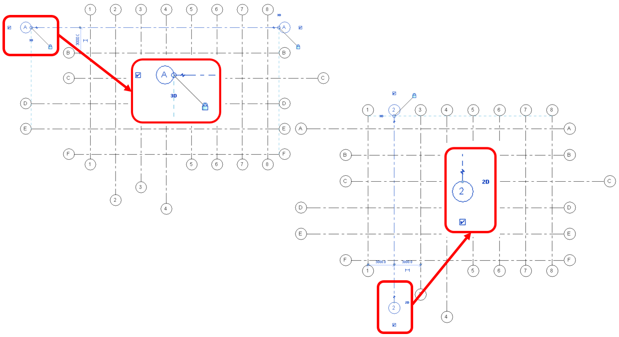
How many times have you had to select individual grid- and level line heads and manually move it into place?
(Psst... There is a faster way) This Revit Recess entry will quickly show you how to achieve just that: Align multiple grid- and level heads with the least amount of steps taken. As can be seen from the image below, a few selected grid heads were unlocked and moved out of alignment to the rest of the grid heads. For other grid lines, the 3D lock was disabled (Thereby only changing grid head locations in the active view, not in all other views)
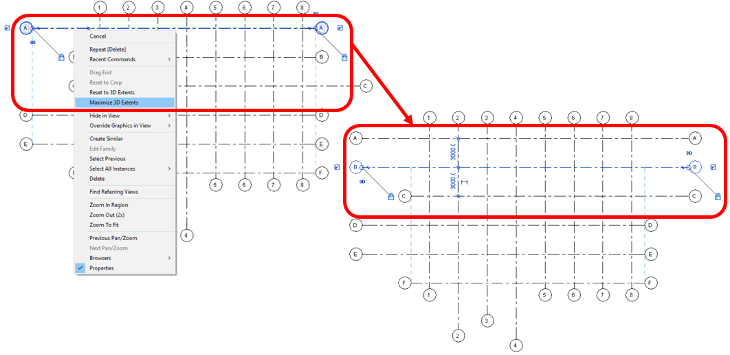
The solution is as simple as selecting an unaligned grid(s), right clicking and invoking the Maximize 3D Extents command.
The Maximize 3D Extents function works for grids, as well as levels.
Whenever a grid or level has been made a 2D element, as can be seen from the image below, naturally the Maximize 3D Extents command does not make any changes (As the elements do not have a 3D function anymore)
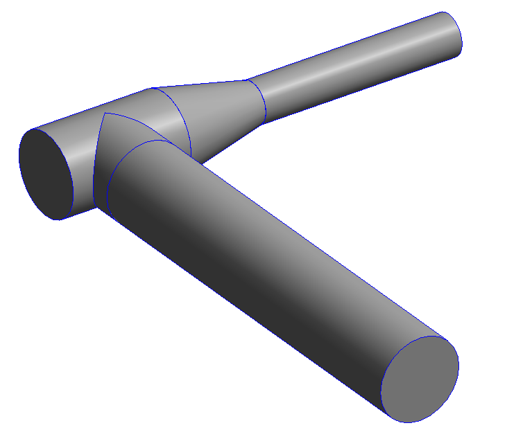
The duct/pipe insulation and lining functionailty in Revit is regularly used in the project environment. However, when the requirements of creating your own family arises, many users struggle to insulate and/or line a custom made fitting or piece of equipment.
This Revit Recess entry will explain the behaviour and characteristics of insulation and lining. The keyword here is Connectors. The image below is of isolated round duct sections where no insulation or lining has been applied yet.
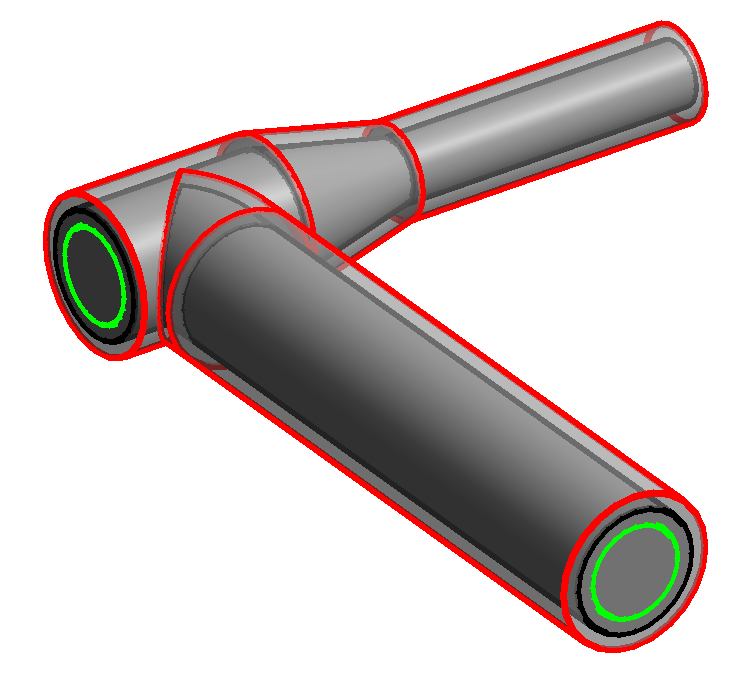
By default, the connectors attached to the T-Piece is the same size as the duct attached to it. The 25mm Insulation is highlighted in Red, with 25mm Lining highlighted in Green
The image below shows the relationship of the duct connector to the geometry of the T-Piece in the family environment.
What if the connector diameters should change in the family itself, with the geometry staying as is? How would that affect insulation and lining applied to the fittings and its respective ducting in the project environment?
After making the changes above and loading this revised T-Piece in the project, we can now clearly see, especially around the T-Piece, that the Insulation and Lining is added from the MEP connector, and not from the geometry edges.
There are those rare occasions where I get an email or a phone call with the following: "Why are my Revit tags freaking out? My leader lines are miles away from the tag label! I'm going back to AutoCAD!!!"
I always tell my students that Revit was created for people with control issues. YOU tell the program what to do. Revit is not a one-click-wonder that reads your mind. Whatever happens, good or bad, is directly related to user input: Whether from yourself, your colleagues, or others working or collaborating with your project.
This Revit Recess post will explain the why of tag leaders "freaking out".
The image below if of an OOTB (Out Of The Box) Pipe Tag family. The red coss indicates the original position of the family reference planes. Remember that the point where the reference planes intersects, determines the base point of the family relative to your mouse curser. In other words, the family's origin point. The blue cross indicates a "finger fault", where the reference planes were unpinned and moved to this new location.
A label has been added to the family, placed centered to the red cross.
The result of the above is that the tag will be justified to the center of the label. (Note that there is quite a large space between the leader and the label. This is due to the fact that the leader end will be constrained by the blue cross)
Let's try and recreate a tag where the leader freaks out. I have unpinned and moved both the Reference Planes as well as the label I have added previously, quite a distance from the red origin point of the tag family.
The end result?
Should one of your tag family templates have been saved after the reference planes were moved (Whether by mistake or on purpose), a reinstall of the Revit content (Cringe...) should work. Alternatively, try and source an unmodified version of the specific family template from a colleague, the internet, or your friendly reseller.