Search This Blog

Friday 31 July 2015

Quickly Copy/Paste Formulas in Revit

When working with a lot of metadata that needs to be used in another Revit family, copying and pasting the formulas from one family to another can be a tedious and extremely frustrating task (Not to mention being cross-eyed for the rest of the day). 

However, there is a quick solution: By selecting the bottom "border" of the formula field row, one will automatically select all text in that row's column. One can now copy and paste the formula using the Ctrl - C, and Ctrl + V keyboard shortcuts.

It is the small things


Sunday 26 July 2015

Revit Recess on #Twitter

Revit Recess has been configured to post on Twitter with each new blog entry (@HermanRsa). Feel free to comment on the posts, provide feedback and ask questions.

Afterall, there is always a workaround, we just have to find it.

Friday 24 July 2015

Revit Striplights - Continued

Barney Stinson: Guys, I'm going through something kind of hard. Since Quinn and I broke up she's gone back to dancing at the Lusty Leopard. And it's just really tough...
Ted Mosby: Because you have to find a new strip club?
Barney Stinson: I have to find a new strip club! I've been going to the Lusty Leopard for seven years...

In the previous Revit LED Strip Light entry, two methods were shown to create curved LED striplight paths. Now, I sometimes tend to overthink a problem, so my colleague, Anria Erasmus, reminded me about the simplest solution to the challenge: Material Asset Self Illumination

What better way to REALLY test this out, than to model a strip club in Revit? If I can only now get Barney's approval... 

A cloud render result shows on the image below. I am not too sure where the funny blotches on the LED tubes came from though. This is prevalent in both Advanced and Native cloud render Exposure settings. 

The Panorama Render example can be accessed by playing the video below. 

The in-Revit render do not show the blotches as the cloud render does, but notice how dull the scene looks! This render was done in Revit 2015

In Revit 2016, I have changed the render engine to Autodesk Raytracer. Ja... Not really what I expected, but I am slowly warming up to the funky look.

The Materials Browser is where one can access and change the Self Illumination values of Material Assets. Some testing will need to be completed to get a satisfactory result. 

Seeing that today is Friday, have a laugh at my first can-can girl creation attempt: 

After deciding not to be lazy, I sourced an image from the internet, spent an hour or two to create the family properly and ended up with the result below:


It would have been much easier (looking better as well) to have created the can-can girl as a adaptive component family, but I simply ran out of time.

Monday 20 July 2015

Revit 2016 Service Pack 2 Available for Download

The latest Service Pack for Revit 2016 - SP2, is available for download from your Autodesk Application Manager.

All relevant documentation such as Readme file and Release Notes, can be viewed from the respective link pages below:


Revit 2016 SP2 Readme File
Revit 2016 SP2 Release Notes

Revit 2015 UR 9 for R2 Available for Download

The latest Update Release for Revit 2015 R2 - UR9, is available for download from your Autodesk Application Manager.

All relevant documentation such as Readme file and Enhancement List, can be viewed from the respective link pages below:


Revit 2015 UR9 for R2 Enhancement List
Revit 2015 UR9 for R2 Readme File

Revit Family Error List Updated

UPDATE: The blog entry Revit Families_Error Compilation, has been updated with 5 additional errors, their explanations and solutions.

Friday 17 July 2015

Revit for Interior Design - Part 2

Earlier this year, I wrote a blog entry introducing Revit for Interior Design. Subsequent blog entries delved a bit deeper into Advanced Revit Render settings and creating custom Revit components, such as the Revit Steampunk entry.

In Revit for Interior Design - Part 2, we will investigate how we can make our Sheets show room finishing information, based on a pre-created colour scheme in a colour fill legend. We will be making use of the Schedule Keys schedule option, in which we can pre-create a room style (Complete with finishes), even before the room exists in the project.  

A very simple building was created, in which rooms were placed. By default, these rooms contains basic information for Base Finishes, Ceiling Finishes, Wall Finishes and Floor Finishes

To show all room style designations in a view, we need to create two Project Parameters. The first parameter can be called Room Function. This will be a Text parameter, applicable to Rooms.

The second Project Parameter can be called Room Function Colour. This parameter type needs to be Image and be applicable to Rooms too.

Create a new Room Schedule. It is quite important to ensure you enable the Schedule Keys option, before creating the schedule. We can name this Schedule Keys schedule as Room Style Schedule.

For the purpose of this entry, we can add the following parameters into our Room Style Schedule:
* Key Name
* Room Function
* Ceiling Finish
* Floor Finish
* Wall Finish 
* Room Function Colour

The Schedule Keys schedule will not contain any fields at this stage. This is due to the fact that we need to pre-populate the schedule with the typical finishes that needs to be applied to a room with a certain style. In the Rows panel of the Ribbon, click on the Insert Data Row command. 

We can now enter the number of room styles that will be used in the project and add the required finishes into each room style row. Because we added the Room Function Colour, we can assign a specific colour to a specific room style.

The end-result can look similar to the image below:

When assigning a specific Room Style to the Rooms in our project, from the Identity Data area in our Properties, the -finishes fields will populate according to the desired style. A colour fill legend was added to the view, with the Colour option set to Room Function.


By adding the Room Style Schedule and plan views to our sheet, all Room Styles will be visible even though that style has not yet been assigned to a room.

Monday 13 July 2015

Customize Revit Arrowheads

'It's not just a question of conquering a summit previously unknown, but of tracing, step by step, a new pathway to it' - Gustav Mahler

An area less explored in Revit is the Additional Settings area. Specifically the Leader Arrowhead settings. This entry will "...trace, step by step, the pathway" to the different customization settings we have for Revit arrowheads. We will use the Furniture Tag as an example.

When selecting the Furniture Tag, we edit the Type Properties. In the Type properties dialogue, we will see the property row for Leader Arrowheads. There are quite a few different arrowhead types, but sometimes we would like different representations thereof.

We can now access our Additional Settings dropdown, from the Manage tab, Settings panel. The Arrowheads command can now be accessed.

We will enter the Type Properties of the different arrowheads we saw in the first picture.To create a custom arrowhead, we need to Duplicate a type first, to ensure that we do not overwrite our existing types. Depending on the Arrow Style we are require, we can edit the Fill Tick, Arrow Closed, Arrow Width Angle, Tick Size, as well as Heavy End Pen Weight.

After a few settings have been changed, you will notice that, when editing the properties of our tag, we will now be able to specify that the Furniture Tag family should use the Custom Arrowhead, thereby changing the arrowhead representation.

Monday 6 July 2015

Revit LED Striplight Creation Tutorial

As per Greg Hayslett's request for a tutorial on the creation of a previous blog post: Revit LED Striplights, herewith the steps to create it using both the Generic Line Based method, as well as the Railing method.

Method 1: Strip Light as Line Based Family


Step 1: We need to create two families, the first being a Metric Line Based family. Create a new family based on the Metric Generic Model Line Based family template.

Step 2: Create a Sweep by picking the Reference Line as the path. Create a 10mm radius circle profile to represent the LED tube. You can either now choose a Material for the tube, or Associate the Material parameter. This will allow you to change the tube material in the project environment. 

Step 3: We need a light source to embed (Or nest) inside of the line based family. Create a new family based on the Metric Lighting Fixture family template.

Step 4: Select the Light Source and change the Light Source Definition’s Shape Emittance to Line, and the Light Distribution to Spherical.

Step 5: Load the Lighting Fixture family into the Line Based Family. Select the light source and edit the Type Properties. Change the Initial Intensity under the Photometrics area to 2.00 Watt. Set the Initial Colour as per your preference.

Step 6: Here is the trick:  If you have a straight ceiling line, you will be able to draw a LED tube segment according to the correct size, and create either an array (Cringe) or copy it along the straight path. When you get to a curved ceiling line, you will have to use either the Inscribed- or Circumscribed Polygon Draw tool. We can create a maximum of 32 individual line based segments per polygon draw command. Any unnecessary LED tube segments can be deleted if required. 

When enabling the Light Source checkbox in the Visibility Graphics command for Lighting Fixtures, you will be able to see the “representation” of light diffusion 

Method 2: Strip Light as Railing Family


Step 1: Create a new family based on the Metric Profile family template

Step 2: Using the Line command, create a 5mm radius profile to indicate the LED tube.

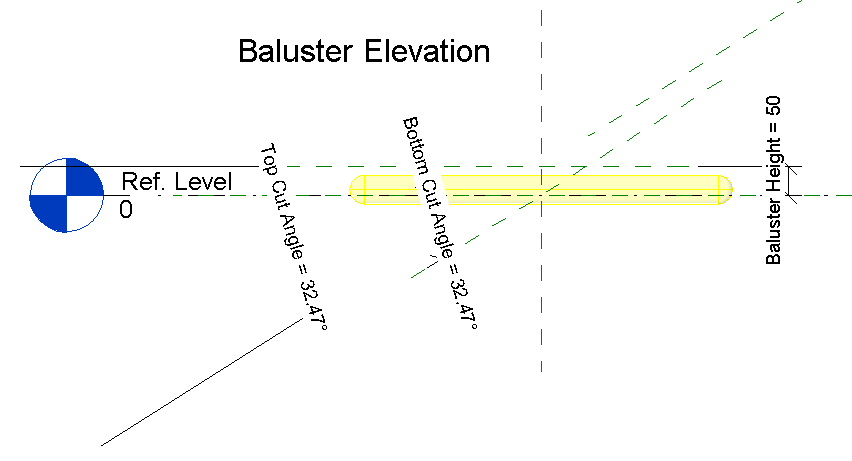
Step 3: For the light source, create a new family based on the Metric Baluster Panel family template.

Step 4: Nest the previously created Lighting Fixture Light Source family (Method 1 – Line based family) into the Metric Baluster Panel family. Position the Lighting Fixture family accordingly.

Step 5: Load the Metric Baluster Panel family, as well as the Rail Profile family into your project. Start the Railing command and duplicate a Railing type. Re-name the railing as Striplight_Railing or similar. Edit the Type Properties of the Striplight_Railing family and edit the Rails. Add a Rail using the Rail Profile family, with a specified offset, using the Plastic, Transparent Autodesk Revit material.

Step 6: Now it’s time to add the baluster (Light Source) to the rail. Edit the Balusters and change the Baluster Family to the previously created Metric Baluster Panel family. You will have to change the Distance From Previous value to get a perfect render representation. I found that in the prvious post, a value of 230mm gave an acceptable result. Remember to set the Posts area for Start Post, Corner Post, and End Post to None.


You will now be able to sketch the railing path using any of the drawing tools you want. Remember to set the Base Offset of the rail to the required Base Offset.


·      Note that if you set the Top Rail option in the rail Type Properties to None, your rail will “break”. The best bet would be to hide the Top Rail per construction view required.

Wednesday 1 July 2015

Revit Devil's Fork Fencing

TIA – This Is Africa: A quote I believe made infamous by the blockbuster Blood Diamond. This entry will focus on another unfortunate TIA necessity here in South Africa: Security. Most residential developments are now taking place in Security Complex's, as it provides some kind of (false, in my opinion) confidence that the chance of crime occurring at your premises are less likely.


None the less, let’s turn a negative into a positive. Why not model the typical middle-class South African security barrier – Devil’s Fork Fencing, in Revit? Following the layout of a previous blog post: Parametric Revit Scaffolding, the first image will focus on the different component types a Devil’s Fork fence segment is typically made of.

Assembled, complete with bars, braces, bolts and washers, the fence actually doesn’t look too bad.

One thing to note however, is that I modeled the Razor Wire a bit thicker than what it would be in reality, for rendering purposes.

The end result can look similar (or even better) than the image below:

As a sidenote: I still cannot understand why Leonardo DiCaprio didn't win an Oscar for his performance. Brilliant film!