The latest Update Release for Revit 2015 R2, UR8, is available for download.
All relevant documentation such as Readme file and Enhancement List, can be viewed from the respective download link pages below:
Revit 2015 UR8 Direct Download
Revit 2015 UR8 Enhancement List
Revit 2016 UR8 Readme File
Thursday 28 May 2015
Revit 2016 SP1 Available for Download
The latest service pack for Revit 2016 is available for download.
All relevant documentation such as Readme file (Containing the Product Enhancements documentation), can be viewed from the respective download link pages below:
Revit 2016 SP1 Direct Download
Revit 2016 SP1 Readme File
All relevant documentation such as Readme file (Containing the Product Enhancements documentation), can be viewed from the respective download link pages below:
Revit 2016 SP1 Direct Download
Revit 2016 SP1 Readme File
Tuesday 26 May 2015
Introduction to InfraWorks 360: Model Builder
You just gotta love Autodesk software!
Last week I attended the Autodesk One Team Conference in Berlin, where the Autodesk team of Mohammad Abou Assali, Hany Shabana and Niyazi Kemer presented a module on InfraWorks 360 for Architects. It was a real eye opener for myself, as I have limited exposure to the software. Yes, one can say I am very excited to start playing around with InfraWorks 360.
This entry is a little taster to what one can expect using InfraWorks 360. There are hundreds of really good YouTube videos out there, so instead of gossiping over Facebook or looking at other people's Instagram holiday photos, rather spend some time productively doing some research. Autodesk uploaded a very useful What's New in InfraWorks 360 video to Youtube, presented by Eric Chappel, which can be accessed by selecting this link.
In the InfraWorks Welcome Screen, to activate the Model Builder functionality, select the Model Builder icon, as per the image below.

We will now be able to search for a specific project location using Bing Maps (If I remember correctly). The example we will use is the V&A Waterfront in Cape Town, South Africa.

We will be able to select either the entire window extent to create the model, draw a rectangle to specify the map, or even draw a polygon. The extent you specify will control the extent of the InfraWorks 360 model. This model will need to have a name before the actual model is being built.

InfraWorks will now prepare your model (Upload it to the InfraWorks 360 cloud.

We will also be able to download our model from the InfraWorks 360 Cloud, to a specific folder location on your local drive/s.

The map boundary in the previous step will now be converted into an InfraWorks 360 model. If the terrain has elevations set in the map service, these elevations will propagate through to the model. Should some of the buildings have heights, these heights will also show through the model as well.

Even though there are quite a lot of functions within the software program, these functions/commands are grouped in a very logical way. To create a road, one selects the Design, Review and Engineer Roads icon, choose Design Roadways, select the Type of Road, and draw the route. Intersections will automatically be added

Now to answer the big question I am sure everyone has: "Can we design our own roads?". Yes, you most definitely can. I invite you to contact your nearest Authorized Autodesk Reseller and/or Training Provider, and start discussing training options. This is, and always will be, the most effective and fastest way in which you and your staff will become productive users.
Monday 18 May 2015
Reference Point - Measurement Type Explained
Revit reference points are often very difficult to place and space according to certain design requirements. However, there is a solution. This solution is known as the point's Measurement Type property.
We will go through the different Measurement Type options in this entry.
1. Measurement Type - Normalized Curve Parameter

2. Measurement Type - Non-Normalized Curve Parameter

3. Measurement Type - Segment Length

4. Measurement Type - Normalized Segment Length

5. Measurement Type - Chord Length

6. Measurement Type - Angle

Using the methods explained above, a 4-point Bezier curve adaptive family was created, which is fully modifiable, as can be seen from the images below.


Another example of using the Measurement Type functionality is for the placement of feature elements on walls. A simple adaptive family was created to place planting pots against a structure fastened to the exterior walls of a house.


We will go through the different Measurement Type options in this entry.
1. Measurement Type - Normalized Curve Parameter
Identifies the location of the reference point on the line as a ratio to the line length over the total length of the line. Its value can vary from 0 to 1. This parameter displays if Normalized Curve Parameter is selected as Measurement Type
2. Measurement Type - Non-Normalized Curve Parameter
Identifies the location of the reference point along a circle or or ellipses. It is also known as raw, natural, internal or T parameter. This parameter displays if Non-Normalized Curve Parameter is selected as the Measurement Type.
Identifies the location of the reference point on a line by the length of the line segment between the reference point and the measure-from end point. Segment Length is represented in project units. This parameter displays if Segment Length is selected as the Measurement Type.

Identifies the location of the reference point on the line as a ratio of the Segment Length over the total length of the curve (0 - 1). For example, if total curve length is 170', and point is located 17' from one of its ends, the value of the % curve length will be either 0.1 or 0.9 depending from which end you are measuring. This parameter displays if Normalized Segment Length is selected as the Measurement Type.
Identifies the location of the reference point on the curve by the straight line (chord) distance between the reference point and the measure-from end point. Chord Length is represented in project units.
Note: On Bezier splines and circles, the position of the reference point may move if the Measure From parameter is toggled in the Properties palette or with the flip arrows in the drawing area.
6. Measurement Type - Angle
Available for points hosted on arcs and circles. Identifies the location of the reference point along an arc or circle represented as an angle. This parameter displays if Angle is selected as the Measurement Type. It is not available for ellipses or partial ellipses.


Another example of using the Measurement Type functionality is for the placement of feature elements on walls. A simple adaptive family was created to place planting pots against a structure fastened to the exterior walls of a house.


Thursday 14 May 2015
Introduction to Autodesk Showcase
Autodesk Showcase is an extremely useful tool for quickly visualizing and presenting models to your clients. This entry will be a short introduction to the program, but there are quite a lot of additional functionality that will make your presentations stand out. For more information, you can follow this YouTube link, where Brian Mackey presents a general overview of Showcase.
You will be able to use your Revit model in Showcase, by accessing the Suite Workflows command from your Application Menu. You will be able to send your model to either 3ds Max, or Showcase. For Showcase, you can present your conceptual model, create an interactive walkthrough or even create a realistic presentation for rendering and/or animation purposes


We can choose between a wide variety of environments for our model. A Grass Field environment was chosen in this example.

In my opinion, one of the best Showcase features is that one can make adjustments to the scene's lighting, as well as shadows on the fly

Animations, walkthroughs as well as flythroughs can be created by creating shots of the scene.

One can also paint model elements to quickly present another material option to a client.
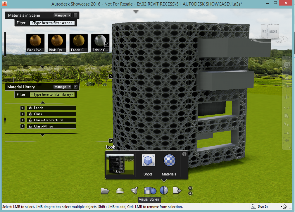
To complete a rendering, one can set the scene's visual style to Raytrace, and save the image to a specific file format.

Painting can easily be done by a window selection as well.
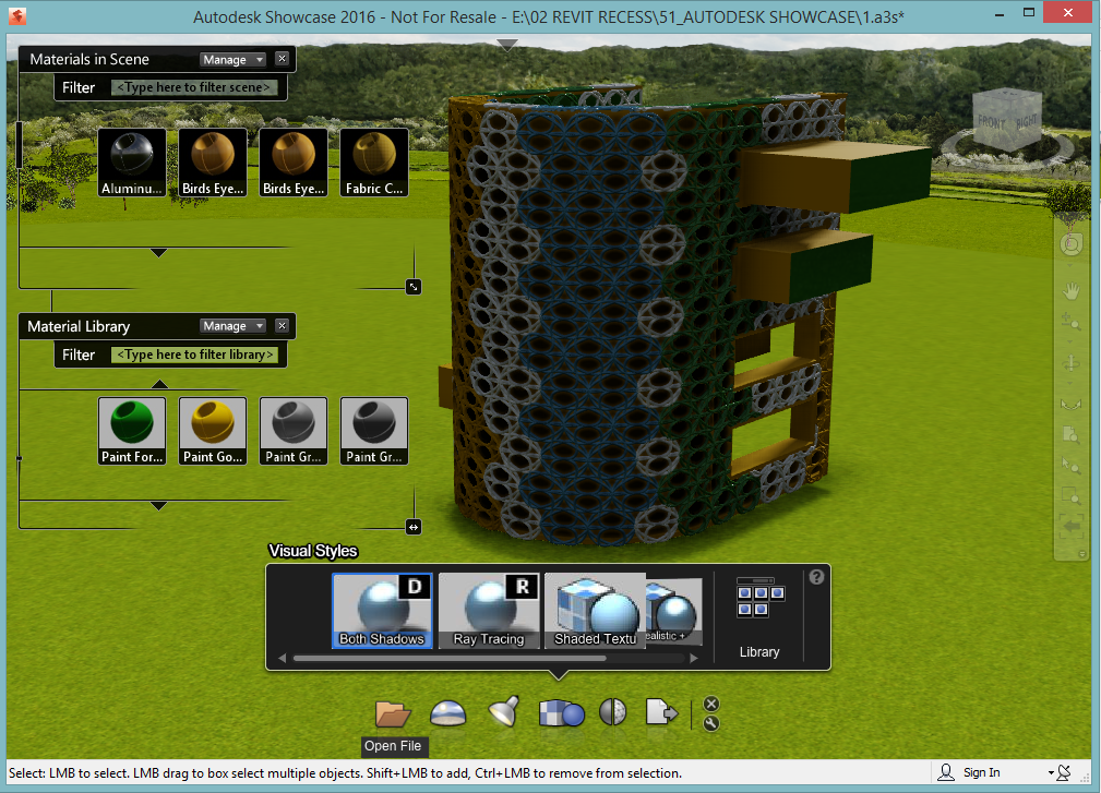
In a nutshell, even though Showcase is not 3ds Max, it is a viable solution for quickly visualizing and representing your designs and/or options to clients
Monday 11 May 2015
Revit Render Quality & Time Analysis
This entry will focus on the advanced render settings one has access to within Revit, as well as the effects each render setting has on rendering times. We will use one of the Basic Sample Project perspective 3D views for this exercise.
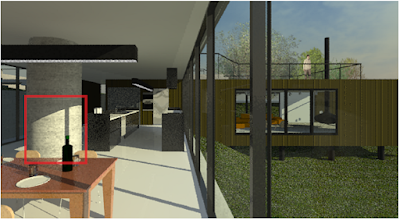
The image below is of the kitchen area, in a Realistic Visual Style

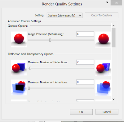
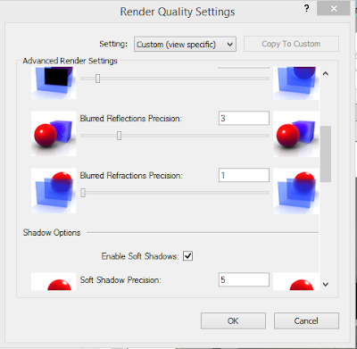
Advanced Render settings can be accessed within the Render command, by editing the Quality Settings. In the Render Quality Settings one can now tweak specific settings before the render is run. The Quality Settings will be based on a Medium render quality.

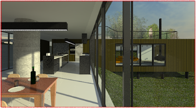
We will use the image below as a control reference for any tweaks we make to the render quality settings. We will go through each quality setting, and test what the effects would be for the minimum, as well as maximum setting on our rendered scene. Red lines will indicate the before and after quality on areas where the most effects can be seen. A rendered time will also be provided for each image.
The control image was rendered using the Medium Quality setting
1.1 Control Image - MEDIUM QUALITY (DEFAULT QUALITY ) - 0m58s

2.1 Image Precision (Anti Aliasing) - LOWEST - 02m37s


2.2 Image Precision (Anti Aliasing) - HIGHEST - 26m58s


3.1 Reflections - LOWEST - 00m34s


3.2 Reflections - HIGHEST - 02m41s


4.1 Refractions - LOWEST - 0m29s


5.1 Blurred Reflection Precision - LOWEST - 0m56s


5.2 Blurred Reflection Precision - HIGHEST - 1m46s


6.1 Blurred Refraction Precision - LOWEST - 0m59s

6.2 Blurred Refraction Precision - HIGHEST - 1m01s


7.2 Soft Shadows - HIGHEST - 2m19s

8.1 Indirect & Sky Illumination - DISABLED - 0m36s
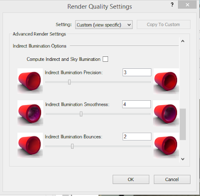

9.1 Indirect Illumination Precision - LOWEST - 0m51s


10.1 Indirect Illumination Smoothness - LOWEST - 0m47s


10.2 Indirect Illumination Smoothness - HIGHEST - 11m09s


11.1 Indirect Illumination Bounces - LOWEST - 0m51s


11.2 Indirect Illumination Bounces - HIGHEST - 1m01s


12.2 Daylight Portals (Doors) - 1m32s


12.3 Daylight Portals (Curtain Walls) - 5m48s


13. BEST QUALITY - MOST ADVANCED SETTINGS - 12m47s

The image below is of the kitchen area, in a Realistic Visual Style

Advanced Render settings can be accessed within the Render command, by editing the Quality Settings. In the Render Quality Settings one can now tweak specific settings before the render is run. The Quality Settings will be based on a Medium render quality.

We will use the image below as a control reference for any tweaks we make to the render quality settings. We will go through each quality setting, and test what the effects would be for the minimum, as well as maximum setting on our rendered scene. Red lines will indicate the before and after quality on areas where the most effects can be seen. A rendered time will also be provided for each image.
The control image was rendered using the Medium Quality setting
1.1 Control Image - MEDIUM QUALITY (DEFAULT QUALITY ) - 0m58s
2.1 Image Precision (Anti Aliasing) - LOWEST - 02m37s

2.2 Image Precision (Anti Aliasing) - HIGHEST - 26m58s


4.2 Refractions - HIGHEST - 0m59s


5.1 Blurred Reflection Precision - LOWEST - 0m56s


6.1 Blurred Refraction Precision - LOWEST - 0m59s


6.2 Blurred Refraction Precision - HIGHEST - 1m01s


7.1 Soft Shadows - LOWEST - 0m53s


8.1 Indirect & Sky Illumination - DISABLED - 0m36s


10.1 Indirect Illumination Smoothness - LOWEST - 0m47s


11.1 Indirect Illumination Bounces - LOWEST - 0m51s


11.2 Indirect Illumination Bounces - HIGHEST - 1m01s


12.1 Daylight Portals (Windows) - 1m56s


13. BEST QUALITY - MOST ADVANCED SETTINGS - 12m47s

Subscribe to:
Posts (Atom)